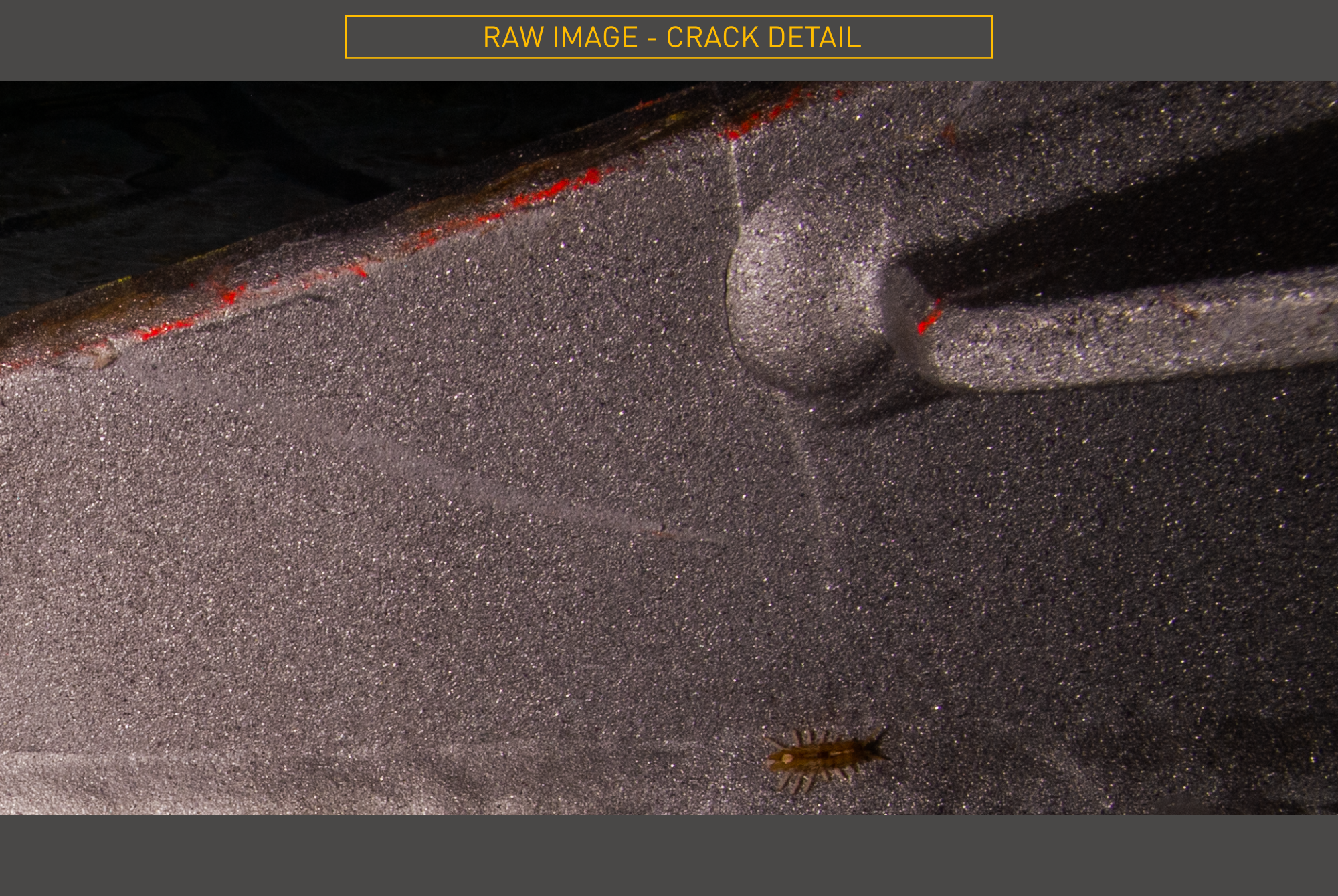
During a routine UWILD hull inspection, a Norwegian operator identified a potential crack on the bilge-keel of a 25-year-old FPSO. With the structural implications of a confirmed defect requiring precise measurement across all three planes (and the asset still in service) the operator needed dimensional data they could take directly to engineering and class.
Two immediate problems presented themselves:
Viewport3 were engaged on the back of an existing relationship, having previously delivered actionable 3D data for the client’s subsea assets in the Norwegian sector.

Following discussions with the marine contractor’s ROV team, a work method was agreed, with equipment and personnel being mobilised to Bergen to join the vessel soon after.
Given the challenge of capturing a hairline crack, this wasn’t a job suited to remote support. The team comprised a day-shift supervisor and a night-shift capture technician, with a digital stills, synchronised strobe system and sufficient processing power to reconstruct the 3D data as it was collected.
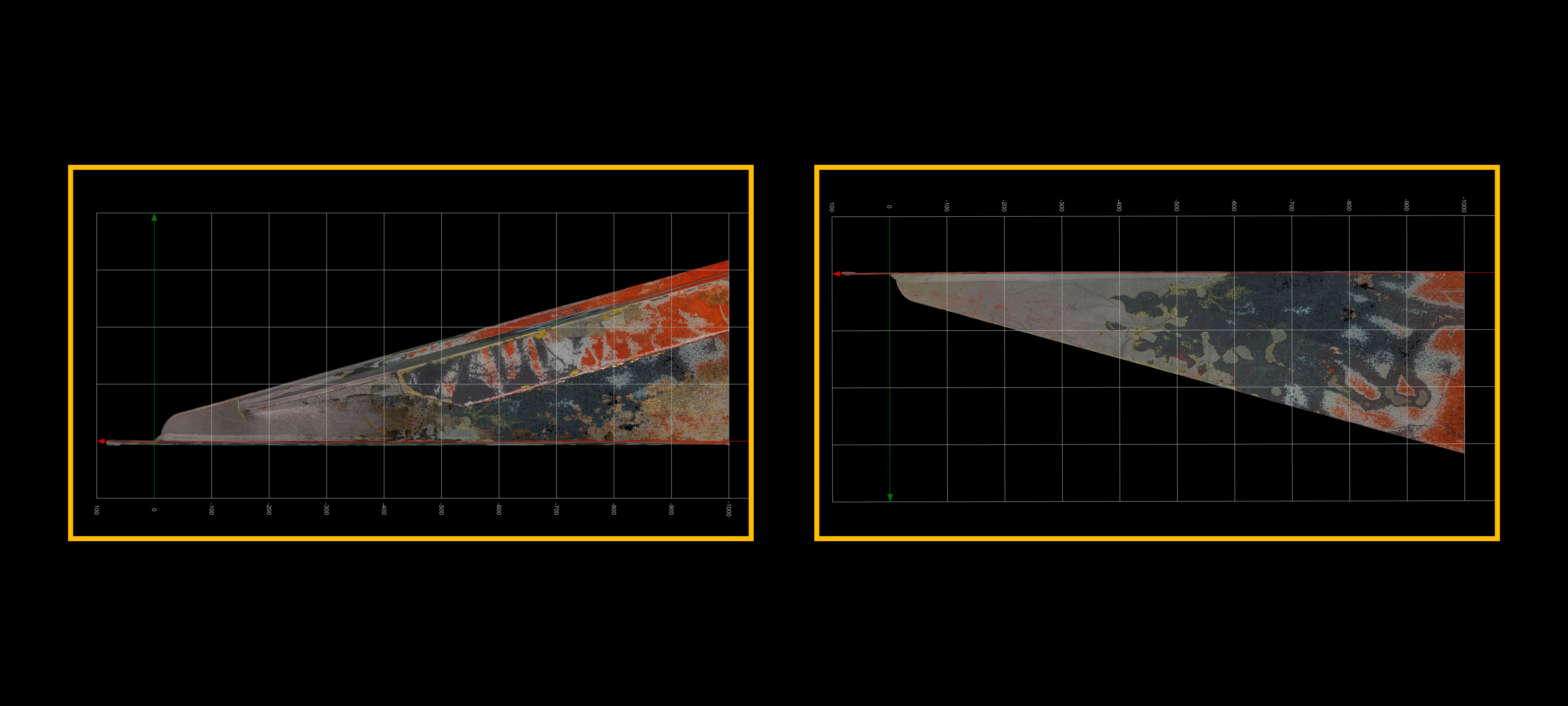
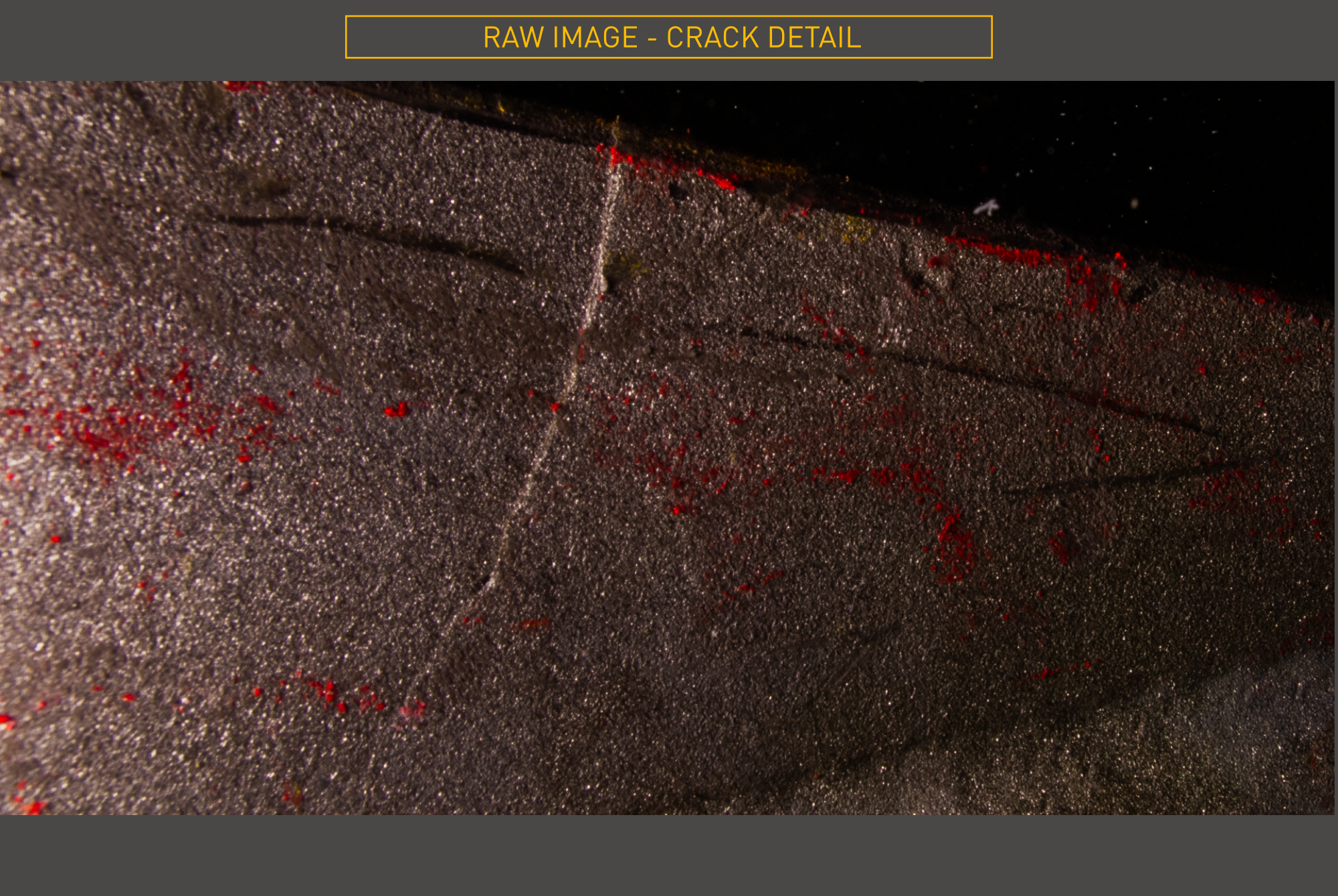
High-resolution still imagery was used throughout, ensuring dimensional assurance of +/- 0.1mm. In-scene scale references were embedded in the dataset — meaning accuracy is verifiable in the data itself, not just assumed at capture time.
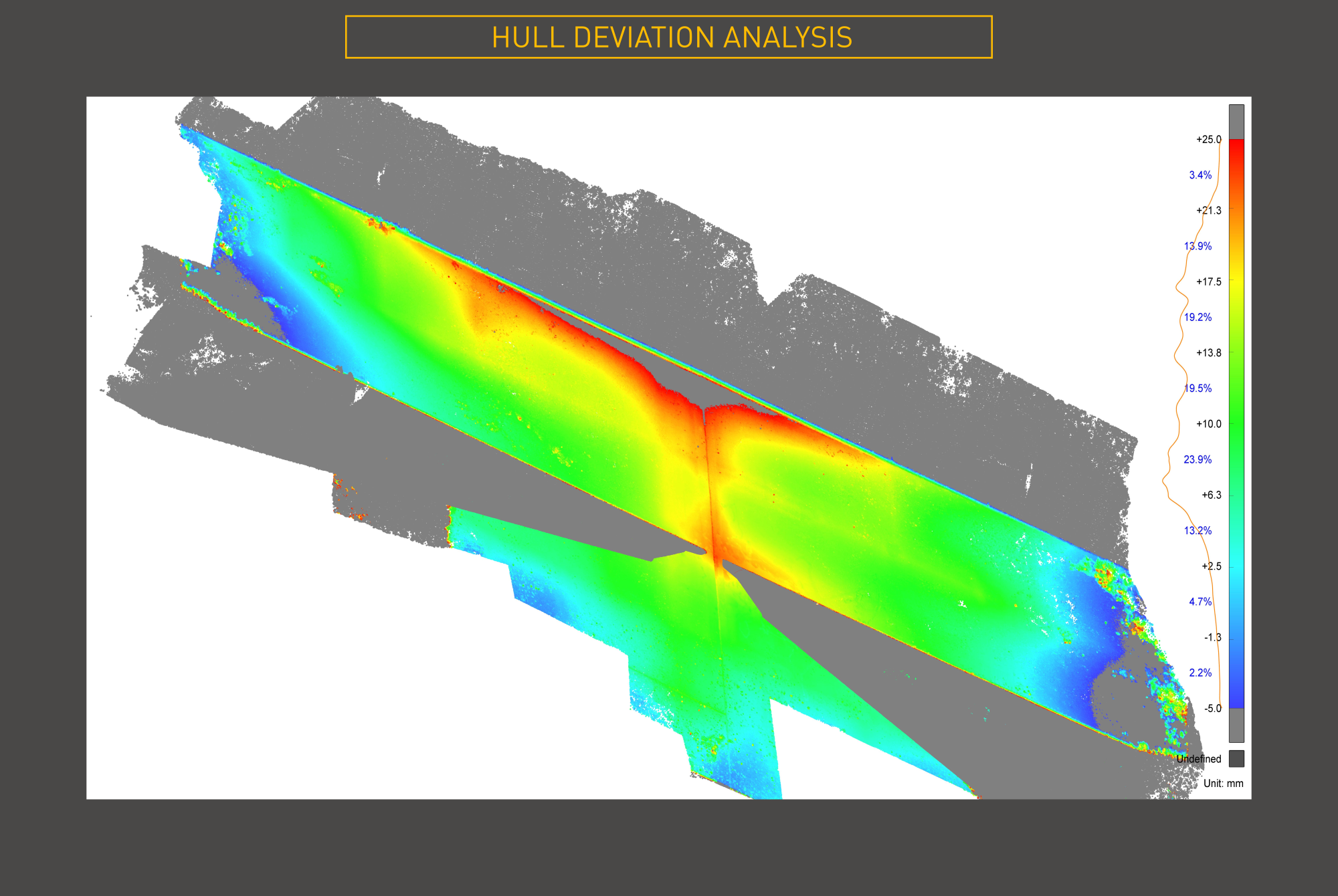
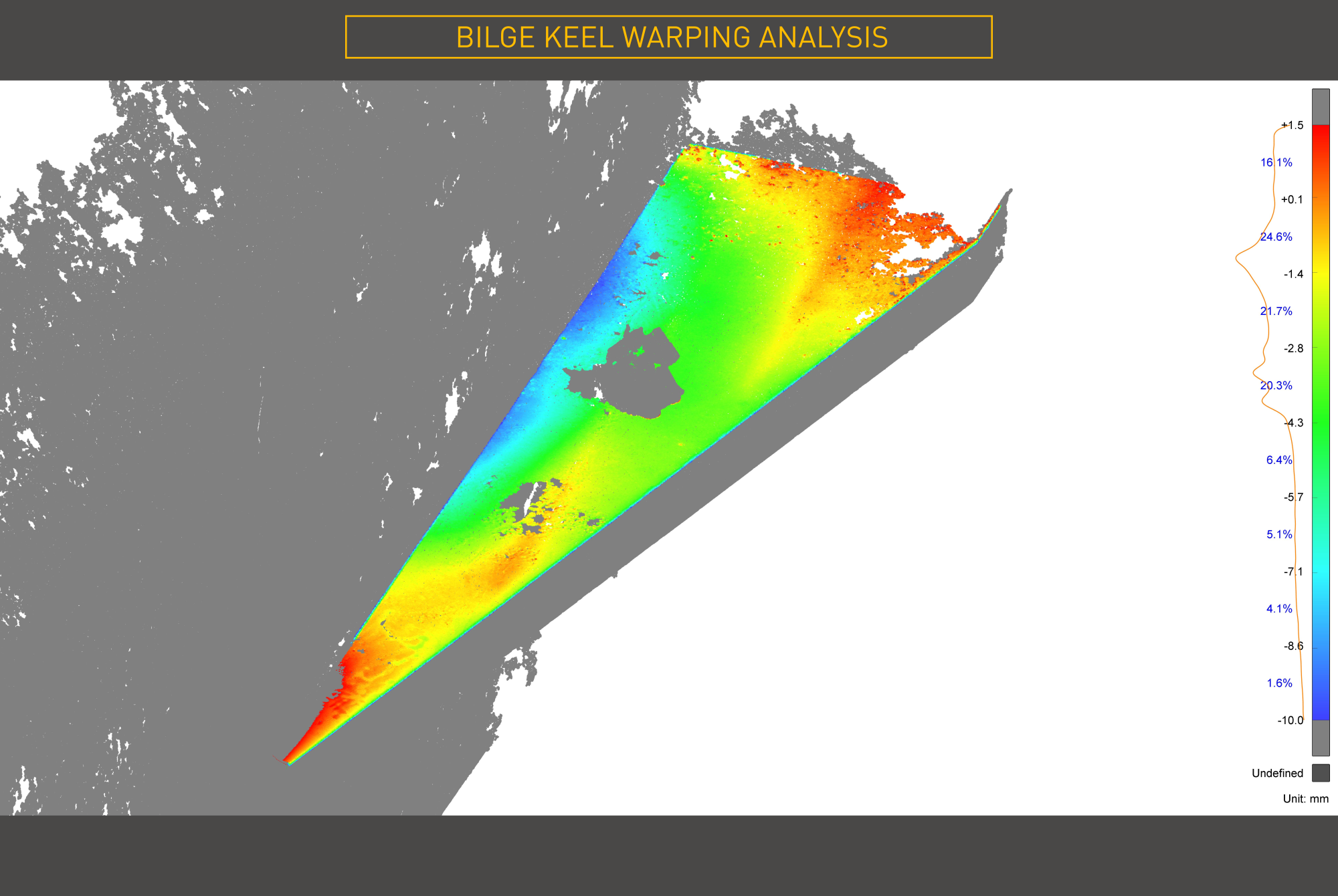
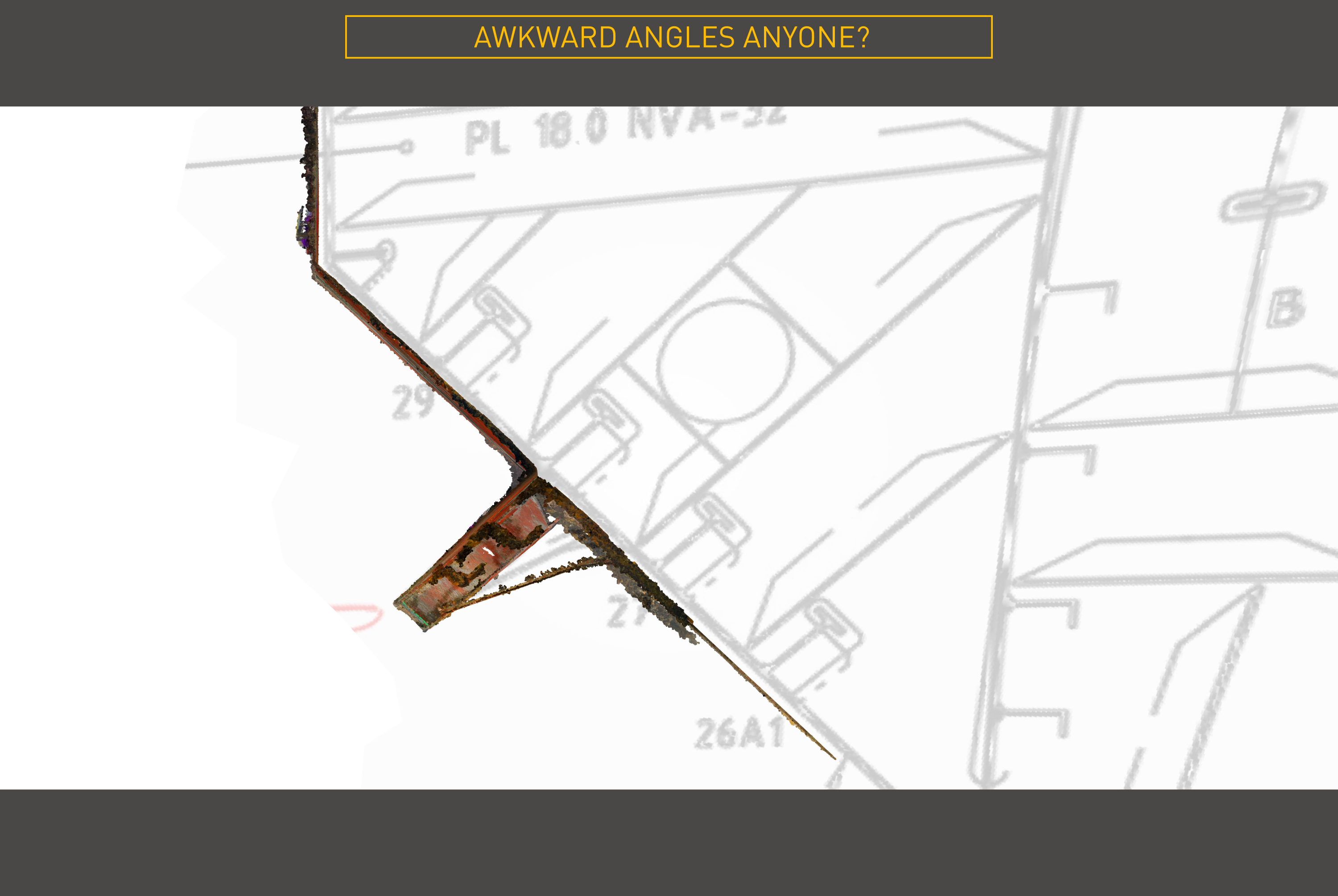
The image dataset was processed into a high-fidelity 3D model and analysed using modern reverse-engineering techniques.
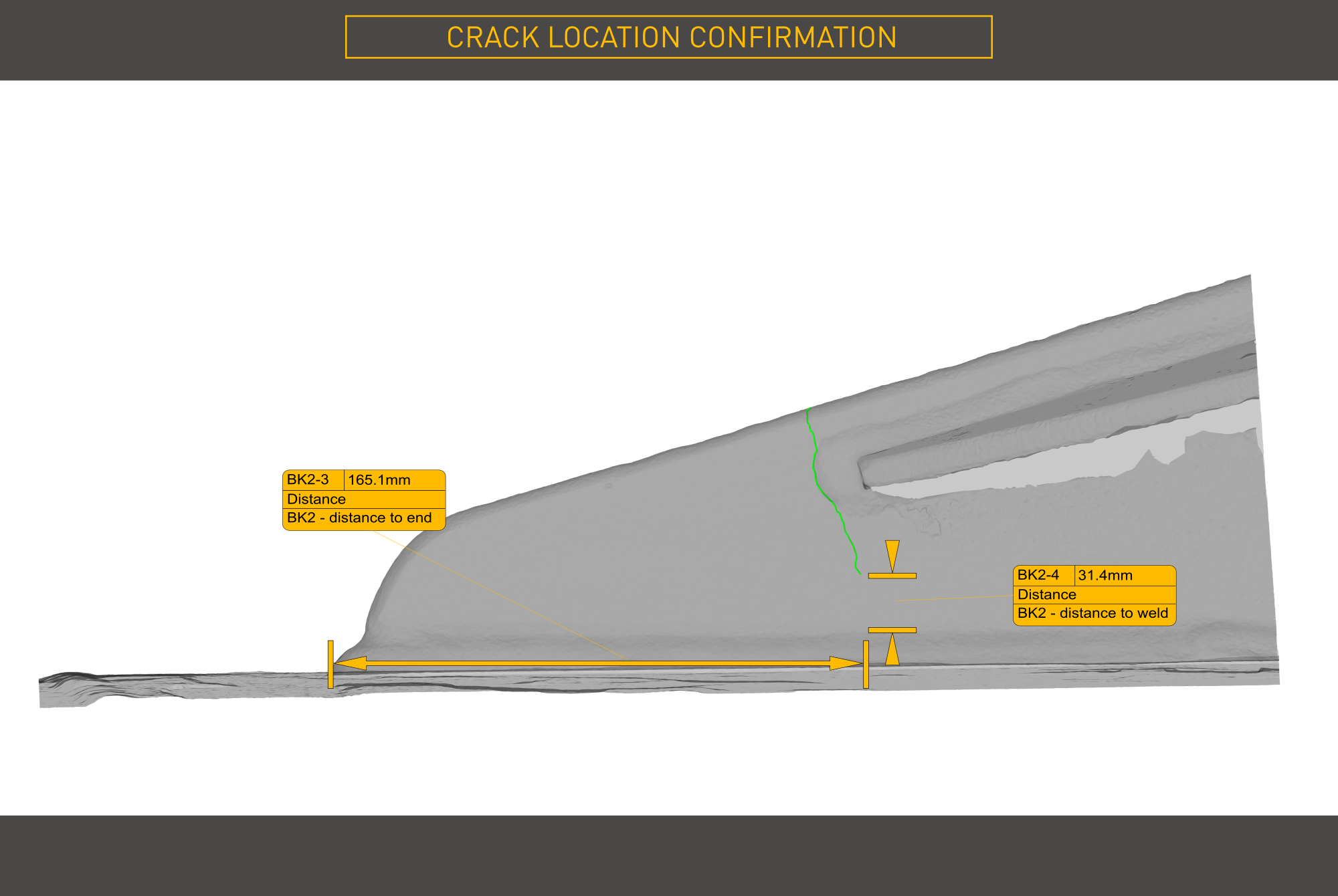
The crack was confirmed. With its presence established, the client instructed Viewport3 to extend the capture area — giving onshore engineering teams the flexibility to assess options for a diver-stage installation and potential removal of the entire bilge-keel.
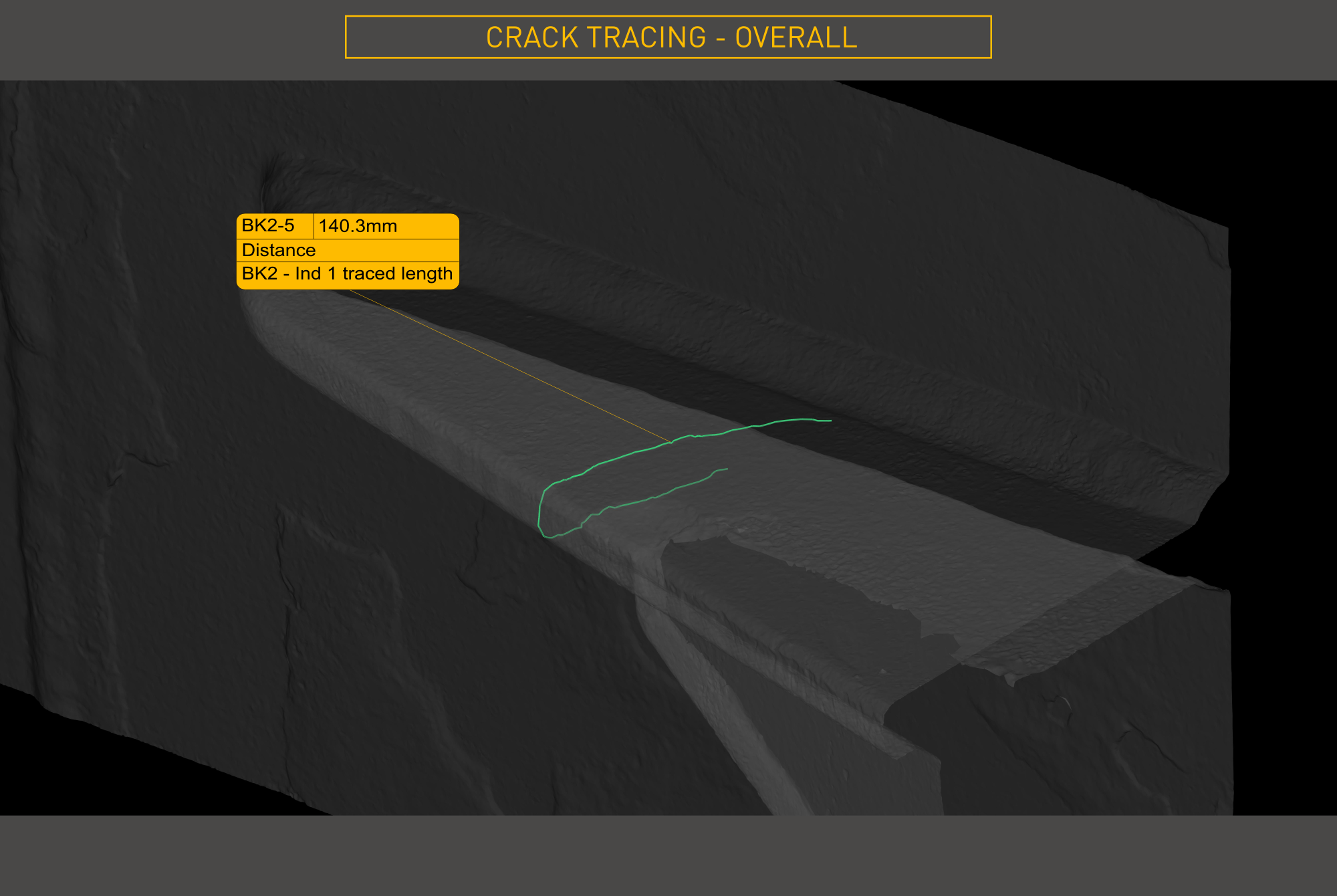
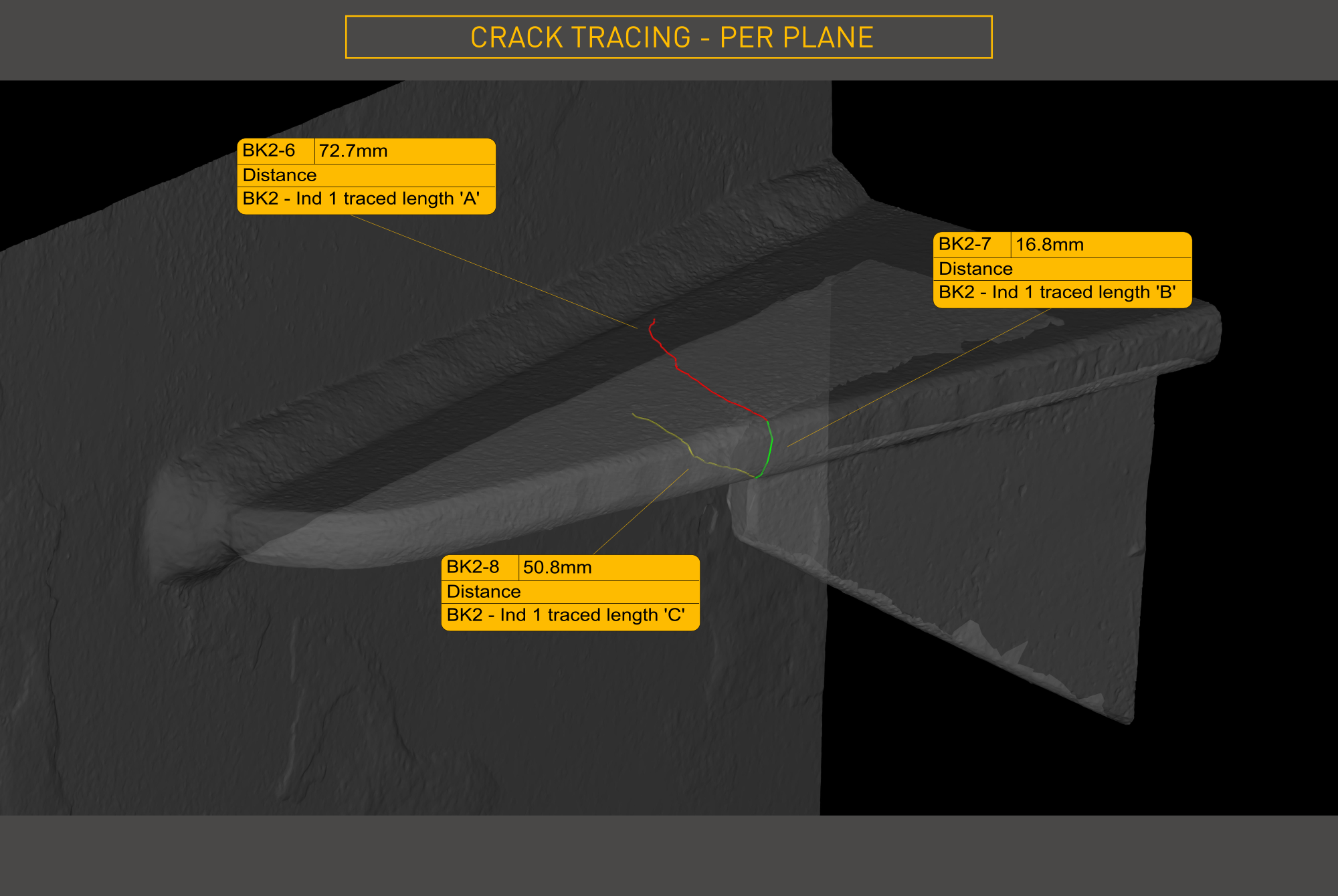
The dimensionally assured outputs issued to the client covered:
The client received everything the onshore engineering team needed to make a fully informed decision — with no further offshore measurement required. This project exemplifies how our subsea photogrammetry inspection service delivers engineering certainty.
